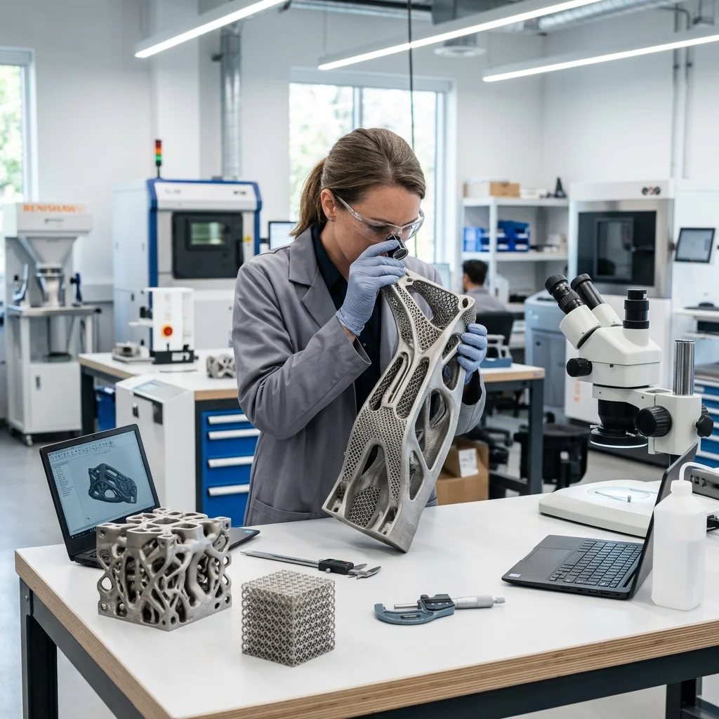
Additive manufacturing is not merely an alternative fabrication method: it is a fundamental paradigm shift in engineering. Traditional design logic, constrained by the realities of milling, turning, and injection molding, no longer applies here. Design for Additive Manufacturing (DfAM) liberates engineers from the shackles of conventional tooling, enabling unprecedented geometric complexity, dramatic weight reduction through topology optimization, and the consolidation of multi-part assemblies into monolithic structures.
However, this newfound freedom comes with its own immutable laws of physics. Maximizing the potential of 3D printing requires much more than simply exporting a CAD model to an STL file. We must design with the layer-by-layer construction process in mind. In this comprehensive guide, we will explore the foundational technical principles of DfAM that will elevate your models from merely 'printable' to industrially optimized masterpieces.
The 45-Degree Rule and Overhang Management
The most fundamental law governing FDM (Fused Deposition Modeling) and SLA (Stereolithography) technologies is gravity. Every new layer must be supported by the material beneath it. As a general rule, overhangs extending beyond 45 degrees from the vertical axis will require support structures. Supports consume additional material, extend print times, and leave behind surface scarring. To eliminate them, employ the Y-H-T rule: structures shaped like a 'Y' print beautifully, 'H' shapes require careful bridging, and 'T' shapes will fail without supports. Design your overhanging features using chamfers or teardrop profiles that gently slope up to 45°.
Orientation and Anisotropic Strength
Unlike injection-molded plastics, 3D printed parts are inherently anisotropic: their mechanical properties vary depending on the direction of measurement. Due to the layer-by-layer fusion process, the Z-axis (layer adhesion) is typically 20-30% weaker than the X and Y axes. As visionary engineers, we must anticipate the load vectors acting upon our parts and orient them on the build plate so that tensile or bending stresses run parallel to the layers, rather than perpendicular to them. Furthermore, print orientation directly dictates surface finish and the location of mandatory supports.
Wall Thickness and Nozzle Dynamics (FDM)
In FDM printing, wall thickness should never be an arbitrary number: it must be a deliberate multiple of the nozzle diameter. If you are using a standard 0.4 mm nozzle, your walls should be multiples of the extrusion width (typically around 0.45 mm). A 1.2 mm wall will print perfectly with exactly 3 perimeters. If you design a 1.0 mm wall, the slicer will generate 2 perimeters and a tiny, inefficient gap-fill in the middle, causing excessive machine vibrations and structural weaknesses. For SLA and SLS, aim for a uniform wall thickness throughout the entire part to mitigate thermal shrinkage and warping.
Tolerances for Moving Parts (Print-in-Place)
One of the true superpowers of additive manufacturing is the ability to fabricate kinematic, print-in-place mechanisms without post-assembly. However, for these mechanisms to function, you must design in the correct tolerances. For FDM, incorporate a clearance of 0.3 mm to 0.4 mm between moving surfaces to prevent them from fusing together. For higher precision technologies like SLA or SLS (Selective Laser Sintering), this clearance can be tightened to 0.15 – 0.2 mm. Always account for the 'elephant's foot' on the first layer, which squishes outward and can fuse the bottom joints of your mechanism. Use a small chamfer at the base to perfectly offset this effect.
Escaping the Solid Paradigm: Hollowing and Infill
Traditional engineering dictates that a strong part must be solid. In 3D printing, a completely solid part is a waste of material, highly prone to warping, and in SLA printing: a recipe for catastrophic failure due to the 'suction cup' effect on the FEP film. Always hollow out massive SLA models and add strategic drain holes near the build platform to allow uncured resin to escape. For SLS, escape holes for unsintered powder are mandatory. In FDM, leverage intelligent 3D infill patterns (like Gyroid or Cubic) that provide excellent isotropic internal strength while reducing the part's weight by up to 70%.
Conclusion
Designing for 3D printing is a constant dialogue between digital creativity and physical physics. By strictly applying the rules of overhangs, part orientation, dynamic tolerances, and structural optimization, we don't just prevent print failures: we unlock geometries that were previously impossible to manufacture. Start thinking additively, apply these DfAM principles, and transform your digital concepts into flawless physical realities.
The full picture
This article is one page from The Big Book of 3D Printing — 700+ illustrated pages covering every technology, material and fix in one reference.
Read it on Kindle →