

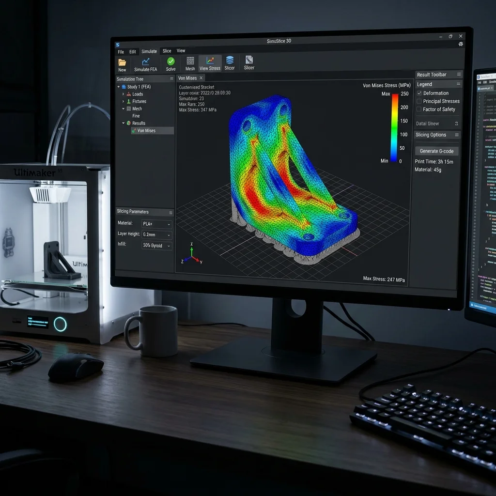
In 2025–2026, Slicer-Integrated FEA transforms the G-code generator from a geometric tool into an engineering simulator. Instead of separate FEA → CAD → slicer pipelines, integrated FEA analyzes part strength with actual print parameters, accounting for anisotropy, infill patterns, and build orientation.
Why FEA in the Slicer?
Standard FEA treats parts as isotropic, homogeneous. But 3D printed parts are anisotropic (Z-strength 30–70% of XY), inhomogeneous (variable infill), and orientation-dependent.
Interactive Filament Selector
Answer 3 quick questions and find the optimal material for your project.
1. What are the mechanical requirements for the part?
2. What temperature will the part operate at?
3. Are there any specific environmental requirements?
Our recommendation:
PLA filament
Ideal for easy printing, model visualization and decorative parts.
Approaches
- Anisotropic Material Model: Orthotropic properties – $E_x = E_y neq E_z$, lower shear modulus $G_{xz}$.
- Infill-Aware Stress Analysis: Simulate real infill structure instead of solid model.
- Build Orientation Optimization: Test multiple orientations, select maximum strength for specific load case.
Pros and Cons
Pros:
- Realistic Analysis: Accounts for anisotropy, infill, and orientation.
- Integrated Workflow: No separate FEA software needed.
Cons:
- Compute-Intensive: FEA requires significant resources.
- Limited Availability: Only ANSYS Additive Suite and nTopology offer AM-specific FEA.
FAQ
Interactive Analyzer for Slicer-Integrated Fea: Engineering Analysis With Real Print Parameters
Select a profile to view detailed analysis.
The full picture
This article is one page from The Big Book of 3D Printing: 704 illustrated pages covering every technology, material and fix in one reference.
Read it on Kindle →Engineer, author of The Big Book of 3D Printing and additive manufacturing expert