

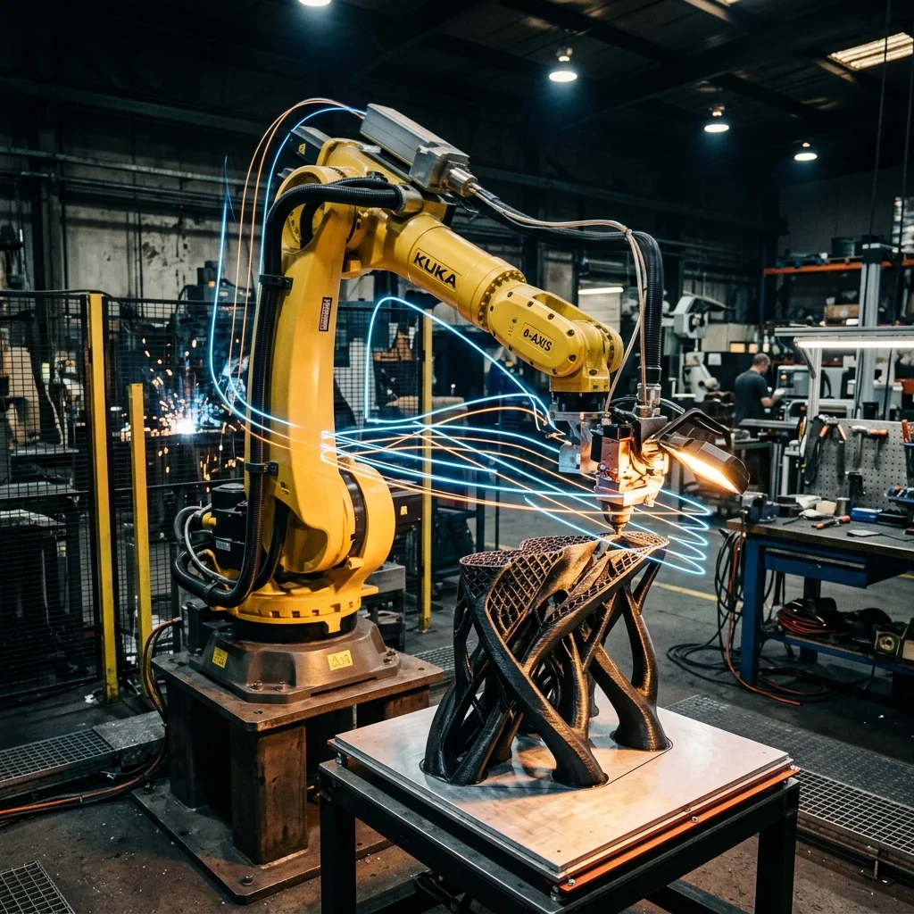
Article #100! In 2025–2026, Multi-Axis Slicing for Robotic Arms liberates 3D printing from 3-axis limitations, enabling 5-axis or 6-axis additive manufacturing through industrial robots. This eliminates supports, enables conformal slicing, and allows isotropic layer orientation.
Why More Than 3 Axes?
Standard 3-axis FDM: staircase artifacts, supports for > 45° overhangs, weak Z-strength. With 5–6 axes: conformal layers, zero supports, layers oriented along load paths.
Interactive Filament Selector
Answer 3 quick questions and find the optimal material for your project.
1. What are the mechanical requirements for the part?
2. What temperature will the part operate at?
3. Are there any specific environmental requirements?
Our recommendation:
PLA filament
Ideal for easy printing, model visualization and decorative parts.
Slicing Approaches
- Conformal Slicing: Curved layers following surface contour.
- Decomposition-Based: Part divided into zones with optimal build directions.
- Continuous Fiber Path: 6-axis fibers following load paths for maximum strength.
Platforms
| Platform | Axes | Type | Status |
|---|---|---|---|
| CEAD CFAM | 6 | Industrial robot + pellet | Commercial |
| Ai Build | 6 | Software for ABB/KUKA | Commercial |
| MX3D | 6 | WAAM robot (metal) | Commercial |
FAQ
Multi-Axis Slicing For Robotic Arms: 5-Axis And 6-Axis Am Calculator
Interactive optimization calculator.
The full picture
This article is one page from The Big Book of 3D Printing: 704 illustrated pages covering every technology, material and fix in one reference.
Read it on Kindle →Engineer, author of The Big Book of 3D Printing and additive manufacturing expert