

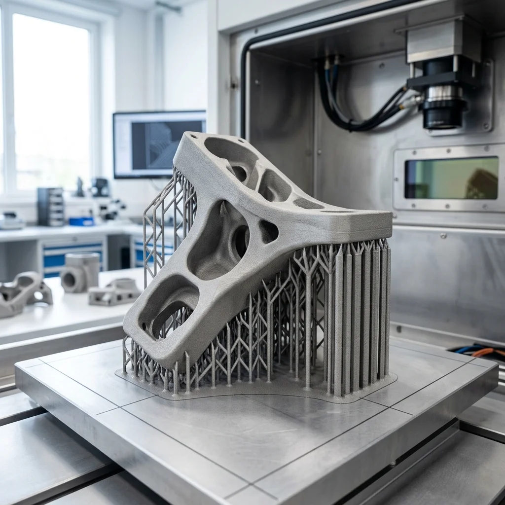
Support structures are the invisible scaffolding that enable overhangs, bridges, and complex geometries in additive manufacturing. Mastering their design not only improves surface finish but also drives material efficiency, reduces post‑processing time, and safeguards ROI across industries from aerospace to biomedical implants.
Fundamentals of Support Geometry
Modern slicers generate three primary support families: linear (grid), tree‑like branching, and lattice infill. Linear supports are quick to generate but create large contact footprints, increasing post‑processing labor. Tree supports mimic natural growth, offering point‑contact footprints that reduce scar marks on delicate surfaces, yet they demand higher computational load and careful orientation to avoid thermal warping. Lattice supports balance material usage and strength, ideal for high‑temperature polymers where heat dissipation is critical. Selecting the right geometry hinges on part orientation, overhang angle, and the printer’s thermal envelope.
Design Strategies to Minimize Waste
Effective design reduces support volume without compromising stability. Key tactics include:
• Angling the part to keep overhangs below 45°.
• Incorporating self‑supporting features such as fillets or chamfers.
• Using detachable sacrificial structures that can be printed separately and assembled post‑print.
Pros/Cons:
– Pros: Reduced material consumption, faster print times, easier removal.
– Cons: Potential for insufficient support on steep overhangs, increased design iteration.
By iterating these strategies in CAD, engineers can cut support material by up to 30% while preserving dimensional accuracy.
Material Selection and Interface Optimization
Support material choice directly impacts removal effort and surface integrity. For PLA and PETG, soluble PVA offers clean dissolution but adds chemical cost; for high‑temperature alloys, breakaway nylon blends are preferred. Interface layers (often a thin “interface” extrusion with reduced density) act as a buffer, minimizing surface imprint. Cost Breakdown:
– Support filament (PVA or nylon): $25 per kg
– Post‑processing labor (removal, cleaning): $15 per hour
– Printer wear (nozzle erosion): $5 per 100 hrs
Total:
Step‑by‑Step Implementation Workflow
A repeatable workflow ensures consistent quality and predictable budgets.
Step 1: Import the CAD model and evaluate overhang angles using built‑in analysis tools.
Step 2: Choose the support family (tree, linear, lattice) based on surface finish requirements.
Step 3: Configure support density (typically 10‑20%) and enable an interface layer of 0.2 mm.
Step 4: Run a test slice, inspect generated supports, and adjust orientation if needed.
Step 5: Export G‑code, monitor the print, and document support removal time for future ROI calculations.
Business ROI and Industry Case Studies
Aerospace firms report a 12% reduction in part weight when optimizing supports for titanium lattice structures, translating to fuel savings of up to 5% over a fleet’s lifecycle. In medicine, patient‑specific orthopedic implants benefit from soluble supports that eliminate hand‑finishing, cutting labor costs by $200 per unit. Robotics companies leverage tree supports to fabricate lightweight lattice brackets, achieving a 20% faster time‑to‑market. Across sectors, the average ROI period for investing in advanced support software and training is 8‑12 months, driven by lower material waste, reduced post‑processing labor, and higher first‑pass yield.
The full picture
This article is one page from The Big Book of 3D Printing: 704 illustrated pages covering every technology, material and fix in one reference.
Read it on Kindle →Engineer, author of The Big Book of 3D Printing and additive manufacturing expert